Abstract
A basic tenet of "Ubiquitous computing" (Weiser, 1993 [13]) is that technology should be distributed in the environment (ubiquitous), yet invisible, or transparent. In practice, resolving the seeming paradox arising from the joint demands of ubiquity and transparency is less than simple. This paper documents a case study of attempting to do just that. We describe our experience in developing a working conference room which is equipped to support a broad class of meetings and media. After laying the groundwork and establishing the context in the Introduction, we describe the evolution of the room. Throughout, we attempt to document the rationale and motivation. While derived from a limited domain, we believe that the issues that arise are of general importance, and have strong implications on future research.
Keywords:
case studies, CSCW, intelligent systems, reactive environments, home automation, design rationale, office applications
Introduction
The convergence of computational, communications and audio/video technologies is having an ever- increasing impact on human-machine interaction. The problems introduced by new applications, users and contexts are prompting new ways of thinking about systems and design. "Ubiquitous computing" (Weiser, 1993 [13]) and "Augmented Reality" (Wellner, Mackay & Gold, 1993 [14]) are two examples of this new thinking. The basic tenet of UbiComp and Augmented Reality is that systems should be embedded in the environment. The technology should be distributed (ubiquitous), yet invisible, or transparent. While the theory is appealing, in practice, resolving the seeming paradox arising from the joint demands of ubiquity and transparency is less than simple. This paper documents a case study of attempting to do just that. We describe our experience in developing a working conference room which is equipped to support a broad class of meetings and media for both same place and different place participation. The work is still "in progress," yet it is sufficiently well advanced that we believe that the timely documentation of our experience will be of benefit to other researchers.After laying the groundwork and establishing the context, we describe the evolution of the room in more-or- less chronological order. We trace the development of the room from manual control, to manually-driven computer control, to context-sensitive reactive automation -- all the while striving towards the goal of simultaneous ubiquity and invisibility. What we present is not a simple "show and tell" story. Throughout, we attempt to document the rationale and motivation. Since these derive from the observations of the specifics of use, our story is somewhat bound in the details of the application and technology of the case study. While derived from a limited domain, we believe that the issues that arise are of general importance, and have strong implications on future research.
Background Context
Over the past five years, we have been involved in studying distributed collaborative work, most recently as part of the Ontario Telepresence Project (Riesenbach, 1994 [8]), and earlier as part of the Cavecat Project (Mantei, Baecker, Sellen, Buxton, Milligan & Wellman, 1991 [7]). This work grew out of research at Rank Xerox EuroPARC (Buxton & Moran, 1990 [4]) and the Media Spaces project at Xerox PARC (Bly, Harrison & Irwin, 1993 [3]).In contrast to work such as Colab (Stefik, Foster, Bobrow, Kahn, Lanning & Suchman, 1987 [10]), our research has focussed mainly on supporting social transactions centered on the offices of the individuals, rather than meeting rooms. Increasingly, however, we have been working towards providing an integrated foundation to support both meeting room and office based collaborative work.
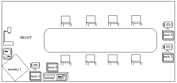
FIGURE 1. Conference Room Equipment. Electronic attendees are given a choice of locations appropriate to the variety of social roles in meeting scenarios.
In the process, we were strongly influenced by the emerging ideas of ubiquitous computing and augmented reality. In particular, we were interested in exploring their affordances in preserving the fidelity of conventional social distance/place/function relationships. An early example of this was the use of video "surrogates" employed in our four-way round-the-table video conferencing system, Hydra (Sellen, Buxton & Arnott, 1992 [9]). The driving function here is the notion that for each location in architectural space for which there is a distinct social function, the affordances should be provided to enable that function to be undertaken from that location by any party, be they attending physically or electronically.
We will see examples of this in practice later in the paper. For our purposes now, note the physical distribution of technology that this implies; hence, our interest in the Ubicomp approach. The inevitable problem that arises, however, is as follows: once the equipment implied by this approach is deployed, how can its use and potential ever be accessed within the user community's "threshold of frustration?" To a large extent, the rest of this paper documents our efforts to answer this question. In our attempts, we learned a lot about what worked and what did not, as well as methods of testing ideas and designs.
The Anatomy of the Room
The room which is the object of study is illustrated in Figure1. It is equipped to support activities such as:- Videoconferencing from the front of the room (permitting remote presentations) or back of the room (permitting remote participants to attend meetings as part of the audience)
- Video playback from both local and remote sites
- Meeting capture via videotape
- Electronic collaborative whiteboard that can be driven locally or remotely, such as described by Elrod et al. (Elrod, Bruce, Gold, Goldberg, Halasz, Janssen, Lee, McCall, Pedersen, Pier, Tang & Welch, 1992 [5]).
- Support for computer demonstrations, run either locally or remotely
- Overhead projection using video document camera capable of being seen locally and remotely
As the amount of equipment and potential functionality increases, so does the cognitive burden on users. With conventional approaches, presenters must handle multiple remote controls and explicitly establish connections between various devices. Consider, for example, the possible problems of switching from an overhead slide to a videotape sample. On what screen does the video appear? Is it the same one as for the overhead? How is the connection established? Users often complain that control of the equipment is confusing and overly complex. Presenters must either interrupt their talk to manipulate the environment, or simply avoid using the technology because it requires too much effort.
Even if all of these issues are resolved for the local audience, what does the remote person see, and how can one be sure that this is what the presenter intended? These, and a myriad of related problems confront the baffled user. We have not even addressed the basic issue of how the user turned on all of the equipment in the room, initially. Where are all the switches and controls?
While our usage studies indicated that we were trying to incorporate the correct functionality and deploying the components in more-or-less the right locations, our work had not really begun. Regardless of the tremendous potential existing in the room, if the complexity of its use was above the threshold of the typical user, the functionality simply did not exist in any practical sense.
HISTORY
The configuration of hardware and software in the meeting room went through a number of iterations, and continues to evolve. An important concern in our design efforts has been to ensure that users of the room can continue to use whatever tools and techniques with which they are comfortable, for example, using a document camera as an overhead or slide projector, and continuing to have a traditional white board. The underlying design principle is to reduce complexity by enabling users to interact with the room using existing skills acquired through a lifetime in the everyday world.In this section we describe the design motivation behind each iteration, discuss the solution taken, and evaluate the results. It should be noted that our evaluation was informal, based on personal experiences and anecdotal evidence.
Initial Environment
Our initial room design was intended to allow remote attendees to participate in meetings. The room was equipped with a camera, monitor, microphone and speaker at the front of the room. This equipment functioned as a video surrogate in an existing media space. In short, it corresponded to most basic videoconferencing rooms.Using this implementation, it was realized through "breakdowns" in meetings that modifications were required. For example, due to the placement of the video surrogate at the front of the room, remote attendees often spent the whole meeting watching the back of the presenter's head. At the same time, local attendees were distracted from the presenter due to the inappropriate location of the remote participant(s) at the front of the room, in the speaker's space. (Note that this situation is the norm in an embarrassingly large number of videoconferencing rooms.) It was clear that different locations of video surrogates were needed for the different social roles of meeting attendees.
First Iteration
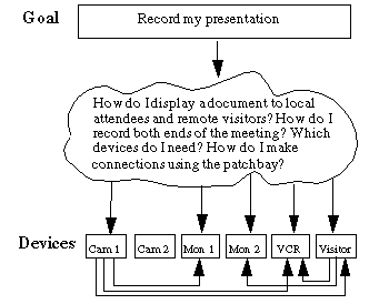
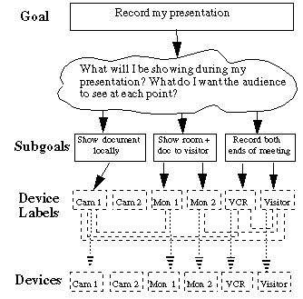
The motivation for the first iteration was to allow remote participants to either present, attend or participate in video meetings. This design involved the addition of three video surrogates at the back of the room. These surrogates were placed at the same height as the conference room table so that remote users would be perceived as sitting around the table. Again, an existing media space was used to support this functionality. This design worked well when remote participants were in the appropriate place. However, users could not select their own positions within the room and it was difficult to move from one location to another, such as when the attendee wanted to change roles and become the presenter.At this stage, the user interface consisted of the set of physical connections between devices themselves. This meant that in order for a presenter to realize a goal, such as "record my presentation," it was first necessary to determine which devices to activate, and then make the appropriate connections between them. Figure2 depicts the user interaction with various devices. The cognitive effort required by the user in order to achieve the high-level goal through direct device manipulation is considerable.
FIGURE 2. Complexity of First Iteration Interface. The inter-device lines represent physical patchbay connections, which the user was required to make.
Second Iteration
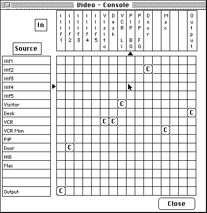
The next step was the incorporation of an software-based matrix to implement the patchbay. This is shown in Figure3.FIGURE 3. Matrix-based interface for controlling equipment (virtual graphical patchbay).
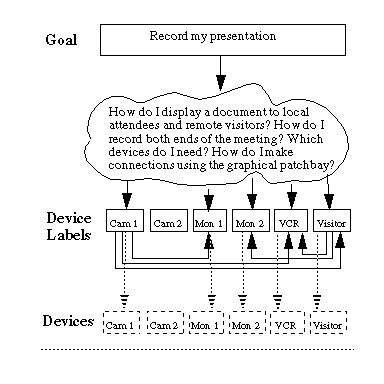
Each row corresponds to a source device (eg. camera, VCR output) and each column to a destination (eg. visitor view of room, video monitor). By clicking the mouse on entry , an audio or video switch would make a connection between sourcei and destinationj. This resulted in considerable time savings, because the user could now establish connections through a graphical user interface, rather than physical wire. However, as depicted in Figure4, since the user was still responsible for all device connections, the cognitive effort remained high.
FIGURE 4. Complexity of Second Iteration Interface. The solid lines represent user interaction and the dashed lines represent tasks performed by the user interface. Note that the user is still responsible for inter-device connections, now made through the graphical user interface.
Third Iteration
To make the system more efficient and reduce the cognitive burden regarding matrix representations, a provision was added which allowed room administrators to create presets as user selections (see Figure5). As illustrated in Figure6, a strong incentive for the development of presets was that they allowed the user to break down a goal into a number of fairly straightforward sub-goals, without concern for the representations of individual devices (Vicente & Rasmussen, 1990 [11]). We found that while this simplified control of the switch, subtle distinctions existed between various presets and users could not decide which ones to choose.FIGURE 5. Presets Menu (DAN). As shown, the Hi-8 video is currently being viewed and the user is considering the selection of the desktop video deck instead.
FIGURE 6. Complexity of Third Iteration Interface, using presets. Now, the user can ignore details of device representation and location, However, presets can be confusing, especially when there is more than one way to accomplish a subgoal.
At this stage, our work was addressing the problems of control at essentially the same level as many commercial room control systems, such as ADCOM's iVue (ADCOM Electronics Inc., 1994 [1]) and AMX's AXCESS systems (AMX Corporation, 1993 [2]).
Buttons and Lights
Two key problems of the previous iteration were the complexity of the user interface and the lack of diagnostics. As a first step towards reducing the complexity, we are presently constructing a set of button and light modules which will be installed on or near each device in the room. Users will be able to make connections simply by pressing the button corresponding to the appropriate source and destination, as shown in Table1. When the first button is pressed, its module light will flash, indicating that the computer is now waiting for the other end of the connection to be indicated. When the second button is pressed, the second module light will flash momentarily, until the computer has made the connection between each device. At this point, both module lights will turn on. The order in which connections are made is unimportant. Either source or destination can be specified first. Additionally, the source or destination of a connection can be changed simply by pressing the appropriate buttons. A special virtual module is required to represent video surrogates.

TABLE 1: Button Action Menu
To illustrate by example, suppose we wish to view a remote participant on monitor 5, and provide this surrogate with the output of our document camera. Pressing the button associated with the surrogate and the button associated with monitor 5 would establish the first connection. The second connection would be formed by pressing the surrogate button and the document camera button. Since the computer knows that monitor 5 is an output-only device and the document camera is input-only, there is no ambiguity as to which connections are intended.
This implementation partly addresses the diagnostics problem of previous iterations through the use of different light states. While the system is working to effect a change, the flashing light indicates to the user that the action is being performed. If a light continues to flash long after a connection has been attempted, a problem exists at a lower level of the system. Obviously, it would benefit us to add diagnostics at these levels as well.
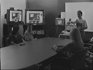
A possible disadvantage of these modules is that they require the user to walk around the room in order to make connections. As an enhancement to this approach, we envision using a laser pointer to point to sources and "drag" them to their destination devices (see Figure7). As a simple example, one could point to a VCR to select it as input, then drag it to one of the monitors for output. Most of the standard connections necessary during presentations could be accomplished in this manner. In order to provide this capability, we will be installing two calibrated laser detectors to cover the front and back of the conference room. This pointer-based connection process, shown in Figure7, could provide efficient device selection without the need for the presenter to change location.
FIGURE 7. Conference Room in use. The speaker is using a laser pointer to select a camera view for the remote visitor.
While the buttons and lights modules offer a substantial gain in simplicity, they cannot adequately replace the high-level control of presets provided in the previous iteration. Users may be reluctant to press five buttons (or point to three devices) in order to play a video tape to local and remote conference participants, when a single preset selection would suffice.
REACTIVE ENVIRONMENT
Our next iteration was motivated by three main points:- We wanted to reduce the overall complexity of operating the room. In particular, we wanted to reduce how much explicit knowledge was required by the user to function effectively.
- We wanted to reduce the intrusion on meetings of managing the operational aspects of the room. If someone wanted to show a videotape, for example, we wanted the user to be concerned only with loading the tape and starting it, not routing the VCR output to appropriate displays.
- One way to achieve both of the above is to simply have the room "driven" by a skilled operator in a
computerized room-control system. While this is the norm in most high-end conference rooms, it was not an
acceptable solution in our case. Our room was used be several groups, many of whom had no vested interest
in the underlying technology. It had to be "walk up and use." The transparent access of Ubicomp had to be
achieved.
To provide a mechanism for such behaviour, the integration of sensors with various devices was required. The output of these sensors allows the computer to determine when certain actions should be taken by the environment, or, in other words, how the environment should react. We call this resulting system a reactive environment. Our reactive environment consists of a set of tools, each of which reacts to user-initiated events. For each tool incorporated into our environment, we must keep in mind the following issues of invisibility, seamlesness, and diagnostics:
- How do we make the tool invisible during normal operation? In order for the system to function effectively, users must not perceive themselves to be involved in a two-party communication. Additionally, the rules of interaction must be made explicit to the user, but these rules should seem natural and not require any understanding of the technology.
- How do we provide a seamless "user override" function for those occasions where the intended behaviour of the tool differs from the automatic? There should not be a need to "argue" with the system if it is not behaving according to the desires of the user. If there is a dispute, the tool should seem to disappear. However, some allowance might be made while the system is "learning" the behaviour of a new user. To minimize the possibility of disputes, reactions to user-initiated events should be conservative.
- How do we provide meaningful diagnostics without a graphical user interface? Currently, if something goes wrong with the system, there is no way to find out what has happened. If extra layers of technology are to be added, it is imperative that diagnostics can provide the location of a problem during failures.
The remainder of this section explains the development of our reactive environment in more detail.
Eliminating Remote Controls
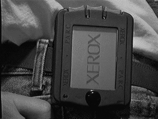
A major problem of the current conference room environment is the effort required to turn on all of the equipment. Setting up the room for a video conference typically involves three switches and three to five button presses on multiple remote control units. Since this process tends to be cumbersome, the simple alternative of leaving most of the equipment turned on all of the time is presently taken. Making use of a motion sensor and a computerized infrared transmitter, capable of generating the same infrared signals as any remote control, we can substantially reduce the interaction necessary between user and equipment. When a user first enters an otherwise unoccupied room, the motion sensor triggers a switch which turns on the lights and activates a transmitter to send the remote control commands necessary to turn on the appropriate devices. If someone is wearing an active badge (Want, Hopper, Falcao & Gibbons, 1992 [12]), for example, the PARC Tab pictured in Figure8, then the room can identify the user and if appropriate, automatically configure itself for that person.FIGURE 8. The Xerox PARC Tab.
Through various sensors, the room can detect most actions that will precede the use of a remote control, and issue the appropriate commands itself, using the infrared transmitter.
Since the user does not need to interact with the computer, nor manipulate remote controls to turn on or configure equipment appropriately, the tool which performs these tasks is completely invisible. In our prototype environment, manual use of remote control units is unnecessary, except on rare occasions where the user wishes to override normal system behaviour.
VCR
Manual operation of a VCR is a relatively straightforward task. However, when the additional burden of specifying a video display or camera source is placed on the user, the equipment suddenly becomes complicated. In a conference environment, context can be helpful in determining the intended behaviour of a VCR. For example, if the play button is pressed, video output should appear not only on a monitor in the local conference room, but also on a monitor in any remote site where there are participants in the discussion. Similarly, if the record button is pressed, the VCR should record video locally as well as from the remote site.Knowledge of whether or not remote participants are involved in a conference is obtained by checking the status of the outside line. VCR functions (eg. play, record, stop) are monitored by polling the VCR interface for user-initiated commands. When a function is selected, our environment can react by establishing the required connections between video sources and VCR inputs, or video destinations and VCR outputs, as appropriate. From the users's perspective, the interface is invisible, since no explicit action beyond pressing the VCR's play or record button was required.
Document Camera
Our conference room has replaced the standard overhead projector typically found in such environments with a document camera, whose output is usually displayed on a large television monitor at the front of the room. Since this monitor is often used for purposes other than viewing documents, presentations involving the document camera can be awkward, especially when a conference presenter wishes the audience to shift its attention from the document to other displays. Even with the buttons and lights interface discussed previously, the need for explicit manual control is too distracting.Fortunately, selection of the document camera view can be automated easily. Using basic image analysis, we can determine whether or not a document is presently under the camera, and whether or not there is motion under the lens. When either a document or motion is detected, the environment reacts by sending the output from the document camera to the display monitor as well as to any remote participants. If no document is detected over a certain timeout period, then the camera is deselected. Again, the tool is invisible. The simple act of placing a document under the camera is sufficient to activate the device To provide a mechanism for seamless manual override, we also wanted a method to force the "re-selection" of the document camera. Our solution was very simple. Whenever document motion is detected after a period of inactivity, the document camera is again selected, regardless of its (assumed) current state.
Digital White Board
The large monitor in our conference room is shared by several applications including the document camera and the digital white board, the latter being a Macintosh computer running any interactive application (see Figure 9). Because of the hardware configuration, users of the white board can automatically write or draw with a light pen instead of the mouse. The only special action required is the selection of the Macintosh computer as the input source to the monitor.Once again, this selection can be automated trivially with the help of a contact sensor on the light pen. Whenever the pen is held, the environment reacts by selecting the Macintosh display automatically and sending this view to remote conference participants as appropriate.
Head-Tracking for Camera Control
By virtue of their location, remote conference participants are currently limited to the view provided by a stationary video camera. In essence, their vision is controlled by a second party, typically the conference presenter, who determines which camera will provide output to the remote site. We considered providing camera selection capability to the remote end directly, but this solution requires additional computer equipment and communications.FIGURE 9. The Digital White Board in use.
We have adopted a more elegant solution, which requires no additional equipment beyond a video camera and monitor on the remote end, yet which allows the remote participant far more control over the received view. We treat the remote monitor as a window through which the local room can be viewed. Applying a head-tracking algorithm to the video signal, we can determine the position of the remote participant's face in relation to his or her monitor. This position is then used to drive a motorized video camera locally. When the remote participant peers to the left or right, the local camera pans accordingly. Similarly, when the remote participant moves closer to or further from the monitor, the local camera zooms in or out.
Evolution Summary
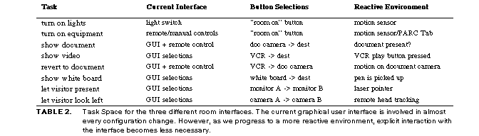
Table2 summarizes the evolution of our reactive environment by examining the task space of our conference room environment. The sensors and sensing techniques previously described have now been integrated into our prototype reactive conference room, as demonstrated in Figure 10.
DYNAMIC FIGURE 10. (QuickTime movie, about 10 mb)
QuickTime video of the Reactive Room.
CONCLUSIONS
In this paper, we have reported our experience to date. This project is ongoing, however, and there remains a great deal to do. Up to now, we have been exploring the problem space and building prototypes to test designs. However, the system is not yet robust, nor do we have the knowledge to make it so. A number of problems remain.A standard issue, shared by those working on intelligent agents, is how to deal with exceptions. How do different users specify different behaviours, or how can the system adapt to the evolving desires or expectations of the user?
In another direction, if the room is to make informed decisions based on context, can there be an application- independent architecture for accommodating the shared cross-application knowledge base and heuristics according to which such decisions are made?
Ubiquitous computing holds great promise. For the first time, we have a model that does not confront us with the classic strength vs. generality tradeoff. We no longer have to choose between strong-specific systems and weak- general ones. With Ubicomp, we have the promise of both strength and generality by virtue of the combined power of a family of strong-specific systems working in concert. But the risk is that while any member of the family is easy to use due to its specific nature, complexity and cognitive load maocessing can be carried out by context-sensitive reactive systems. That being the case, our hope is that this work will stimulate research that will make this capability available sooner rather than later.
TABLE 2. Task Space for the three different room interfaces. The current graphical user interface is involved in almost every configuration change. However, as we progress to a more reactive environment, explicit interaction with the interface becomes less necessary.
ACKNOWLEDGEMENTS
Many people have contributed to this project. We would like to thank Bill Gaver for the original head- tracking code, written at the Technical University of Delft and Rank Xerox EuroPARC, Dominic Richens for his work on the early versions of the graphical user interface, and Jie Dai for an early implementation of the infrared transceiver driver. Thanks also to Kim Vicente, George Fitzmaurice, and Kevin McGuire for the useful discussions and feed- back.We also thank Rich Gold, Roy Want, and Norman Adams of Xerox PARC for help with the PARC Tab and Mike Ruicci of CSRI for his outstanding technical support. Special thanks are due to Sidney Fels for the design of the buttons and lights modules, as well as many hours of insightful discussion. Finally, we are greatly indebted to the members of the various research groups who make up the user community of the room. Their patience and feedback has been essential to our work.
This research has been undertaken as part of the Ontario Telepresence Project. Support has come from the Government of Ontario, the Information Technology Research Centre of Ontario, the Telecommunications Research Institute of Ontario, the Natural Sciences and Engineering Research Council of Canada, Xerox PARC, Bell Canada, Alias Research, Sun Microsystems, Hewlett Packard, Hitachi Corp., the Arnott Design Group and Adcom Electronics. This support is gratefully acknowledged.